Vlans are used to isolate traffic, and vlan tags are used to
multiplex/de-multiplex frames (packets) across a single ethernet cable.
Vlans can also be used internally to spilt a single interface into multiple interfaces. When
a network interface is split, the Ethernet cable connected to it becomes a trunk.
A router on a stick is a router with only one ethernet port, which is connected to a
vlan switch. The single ethernet port is split into two or more ethernet ports via
vlans (e.g., VLAN 100 and VLAN 300).
Figure 1 is a diagram of a simple router-on-a-stick. On the switch:
Table 1 are the rules for the switch. Note, that traffic leaving Port 2 goes to
either Port 1 or Port 3 but not both Ports 1 and 3.
Port No.
Vlan Name
Vlan No.
1
2
3
4
5
configure
1
U
U
U
U
U
in
100
U
T
trunk
200
T
out
300
T
U
PVID
100
200
300
1
1
Table 1. Vlan Switching Table for the Simple Router-on-a-Stick in Figure 1.
Traffic Flow
All traffic originating at port 3 and going to the ISP Router or Internet, first goes to
the router-on-a-stick (port 2) with a vlan tag of 300. It is then masqueraded and forwarded
out of the router-on-stick with a vlan tag of 100 and proceeds to the ISP Router -
vice versa for traffic coming from the ISP Router.
If you select the right options,
the Network-Manager will take care of masquerading and forwarding for you. Otherwise,
you have to do this with nftables or iptables.
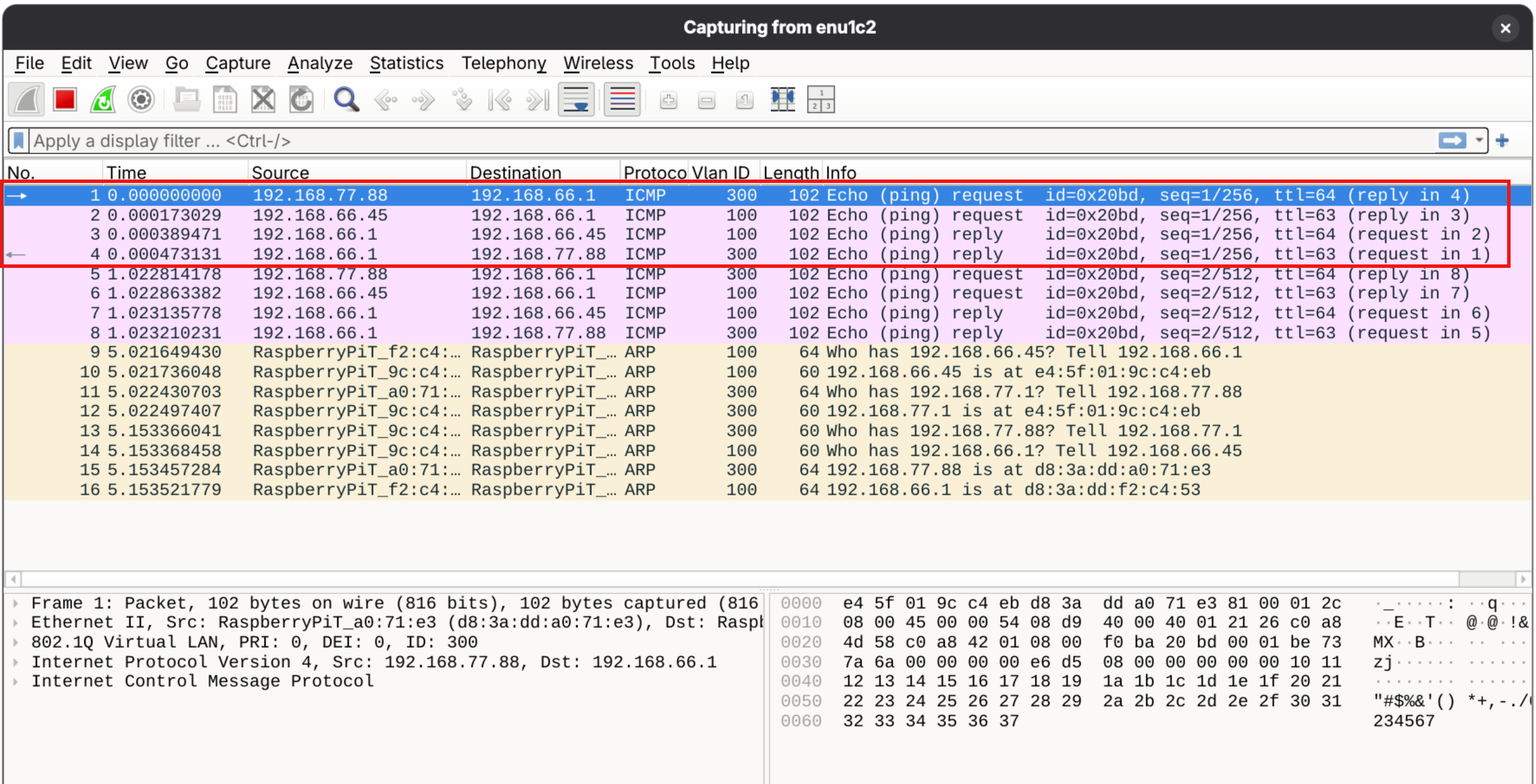
The Wireshark capture below depicts a ping from a host (192.168.77.88) connected to port 3
to the ISP Router (192.168.66.1).
The ping request first goes into the router-on-a-stick with a vlan tag of 300.
The Network-Manager adds masquerading and forwards the ping out of the router-on-a-stick
with a vlan tag of 100.
The ISP Router (192.168.66.1) receives the ping request and sends a response back to
the router-on-a-stack with a vlan tag of 100.
The Network-Manager undoes the masquerade and forwards the response out of the
router-on-a-stick with a vlan tag of 300, and it is received by the host
(192.168.77.88).
You can easily add columns in Wireshark. I added the vlan.id column.
Network-Manager Setting
Minimum Network-Manager Syntax
sudo nmcli con add con-name <connection-name> type vlan dev <interface-name> id
You can specify other Network-Manager commands on the same line as the minimum syntax.
If you do not specify an ifname, the default is "interface-name.vlan-id". For example,
if the interface-name is eth0 and the vlan-id is 100, the default ifname is "eth0.100".
It is common for the con-name and ifname to be the same. It is also common with vlans
for someone to not specify the ifname and use the anticipated default ifname
for the con-name.
For the simple router-on-a-stick in Figure 1, the subnet of the ISP Router is 192.168.66.0/24.
The router-on-a-stick must have a front facing interface in this subnet. For it to be router
and not an access point, it also must have a rear facing interface in another subnet.
The code below assumes that the front facing interface is 192.168.66.45, and that the
router-on-a-stick will dynamically (dhcp) assign hosts connected to it addresses
in the range 192.168.77.81 thur 192.168.77.99.
VLAN 100
sudo nmcli con add con-name eth0.100 type vlan dev eth0 id 100 ipv4.address 192.168.66.45/24 ipv4.method manual ipv4.gateway 192.168.66.1 ipv4.dns 192.168.66.1 ipv6.method disabled
sudo nmcli con add con-name eth0.300 type vlan dev eth0 id 300 ipv4.address 192.168.77.1/24 ipv6.method disabled ipv4.method shared ipv4.shared-dhcp-range '192.168.77.81,192.168.77.99'
1: lo:  mtu 65536 qdisc noqueue state UNKNOWN group default qlen 1000
    link/loopback 00:00:00:00:00:00 brd 00:00:00:00:00:00
    inet 127.0.0.1/8 scope host lo
       valid_lft forever preferred_lft forever
    inet6 ::1/128 scope host noprefixroute
       valid_lft forever preferred_lft forever
2: eth0:  mtu 1500 qdisc mq state UP group default qlen 1000
    link/ether e4:5f:01:9c:c4:eb brd ff:ff:ff:ff:ff:ff
3: wlan0:  mtu 1500 qdisc noop state DOWN group default qlen 1000
    link/ether e4:5f:01:9c:c4:ed brd ff:ff:ff:ff:ff:ff
4: eth0.300@eth0:  mtu 1500 qdisc noqueue state UP group default qlen 1000
    link/ether e4:5f:01:9c:c4:eb brd ff:ff:ff:ff:ff:ff
    inet 192.168.77.1/24 brd 192.168.77.255 scope global noprefixroute eth0.300
       valid_lft forever preferred_lft forever
5: eth0.100@eth0:  mtu 1500 qdisc noqueue state UP group default qlen 1000
    link/ether e4:5f:01:9c:c4:eb brd ff:ff:ff:ff:ff:ff
    inet 192.168.66.45/24 brd 192.168.66.255 scope global noprefixroute eth0.100
       valid_lft forever preferred_lft forever
On the Client Side
The IPv4 address can either be statically assigned or the router-on-a-stick will dynamically assigned one.
For Static Addresses:
sudo nmcli con add con-name eth0 ifname eth0 type ethernet ipv4.method manual ipv4.address 192.168.77.88/24 ipv4.gateway 192.168.77.1 ipv4.dns 192.168.77.1 ipv6.method disabled
For Dynamic Addresses:
sudo nmcli con add con-name eth0 ifname eth0 type ethernet ipv4.method auto ipv6.method disabled
Network-Manager Generated Nftables
Because the eth0.300 (VLAN 300) ipv4.method was shared, the Network-Manager
will not only implement the DHCP protocol and supply ipv4
address from the specified range, but it will also generate
nftables for forwarding and masquerading.
# Generated by Debian 13 (trixie) / Raspberry Pi OS.
table inet filter {
	chain input {
		type filter hook input priority filter; policy accept;
	}

	chain forward {
		type filter hook forward priority filter; policy accept;
	}

	chain output {
		type filter hook output priority filter; policy accept;
	}
}

# Generated by the NetworkManager because ipv4.method was shared.
table ip nm-shared-eth0.300 {
	chain nat_postrouting {
		type nat hook postrouting priority srcnat; policy accept;
		ip saddr 192.168.77.0/24 ip daddr != 192.168.77.0/24 masquerade
	}

	chain filter_forward {
		type filter hook forward priority filter; policy accept;
		ip daddr 192.168.77.0/24 oifname "eth0.300" ct state { established, related } accept
		ip saddr 192.168.77.0/24 iifname "eth0.300" accept
		iifname "eth0.300" oifname "eth0.300" accept
		iifname "eth0.300" reject
		oifname "eth0.300" reject
	}
}
The output of "sudo nft list ruleset", only list rules and suppresses all comments.
The two comments were added to show which tables were produced by what.
The DHCP protocol allows for static addresses,
so you do not have to actually implementing the method shared,
but you need the method to be shared to get the Network-Manager
to generate the nftables.
Allowing Access to the Router's Subnet from an Upstream Host
Figure 3. Router-on-a-Stick - Granting Access from an Upsteam Host.
The nftable created by the Network-Manager only allows traffic that
originates behind the router. That is, it rejects any unsolicited
traffic coming into the router, and this is what a router facing
the Internet should do. However, I have a host that is in front
of the router, and it needs to communicate with host behind the router.
To allow this, I copied the nftable ruleset generated by
the Network Manager, disabled the Network-Manager from
generating nftables, and implemented the copied ruleset
manualy, and finally modified the nftable. There are lots
of steps, but they are straight forward:
Enable nftable:
sudo systemctl enable nftables
sudo reboot
Copy the rules created by the Network-Manager into a file
in the /etc/ directory so they can later be modified.
sudo nft list ruleset > /etc/my_router.nft
At the end of /etc/ntfables.conf add the following
(including the quotations):
include "/etc/my_router.nft"
Stop the Network-Manager from generating nftables
for forwarding and masquerade.
Create a configuration file in "/etc/NetworkManager/conf.d"
such as "no_nft.conf".
sudo vi no_nft.conf
Place the following two lines in the file:
[main]
firewall-backend=none
Enable IPv4 forwarding:
Create a new configuration file in /etc/sysctl.d, such as,
"allow_forwarding.conf".
sudo vi allow_forwarding.conf
Add the following line to the file:
net.ipv4.ip_forward=1
After rebooting, you are back to where you started at, but you
can now modify the old Network-Manager rule file in /etc.
sudo reboot
My modified table is below:
table ip nm-shared-end0.300 {
	chain nat_postrouting {
		type nat hook postrouting priority srcnat; policy accept;
		ip saddr 192.168.77.0/24 ip daddr != 192.168.77.0/24 masquerade

        # added by me on 2026/08/01
        # ip saddr != 192.168.77.0/24 ip daddr 192.168.77.0/24 masquerade
	}

	chain filter_forward {
		type filter hook forward priority filter; policy accept;
		ip daddr 192.168.77.0/24 oifname "eth0.300" ct state { established, related } accept

        # added by me on 2026/08/01
        ip daddr 192.168.77.0/24 oifname "eth0.300" ip saddr 192.168.66.67 accept

		ip saddr 192.168.77.0/24 iifname "eth0.300" accept
		iifname "eth0.300" oifname "eth0.300" accept
		iifname "eth0.300" reject
		oifname "eth0.300" reject
	}
}
Where 192.168.66.67 is the IPv4 address up the upstream host.
Finally, you need to add a route on the upstream host to access the hosts in the subnet:
sudo nmcli con mod eth0 +ipv4.routes "192.168.77.0/24 192.168.66.45".
where 192.168.66.45 is the front facing IPv4 address of the
router-on-a-stick.
The Network-Manager settings for eth0.100 (VLAN 100) and eth0.300 (VLAN 300) are the same
as in the first example.
VLAN 400
sudo nmcli con add con-name eth0.400 dev eth0 id 400 ipv4.address 192.168.88.1/24 ipv6.method disabled ipv4.method shared ipv4.shared-dhcp-range '192.168.88.81,192.168.88.99'
VLAN 500
sudo nmcli con add con-name eth0.500 dev eth0 id 500 ipv4.address 192.168.99.1/24 ipv6.method disabled ipv4.method shared ipv4.shared-dhcp-range '192.168.99.81,192.168.99.99'
Raspberry Pi Enabling VLANS
Most of what I have read on the Internet said that to enable vlans on a Raspberry Pi you need to:
Install the Vlan package:
sudo apt install vlan
Load the kernel module:
sidp modprobe 8021q
I forgot to do this, and it still worked.
WireShark shows the correct tags on frames going to
and from the router. I currently believe that the
Network-Manager has its on vlan package, and it is
handling this.
Implementations
This was implemented on both a Raspberry Pi 5B and a RPi Zero 2W. For the Zero 2W, I had to add
a USB-to-Ethernet adapter. The USB port on to Zero 2W is USB 2.0 and limited to 480 Mb/s maximum.
It was fast enough for web surfing, but it's not as fast as 1GB/s Ethernet.
Maybe the Zero 3w wifi have USB 3.0, which has a transfer rate of 5GB/s.